
Wiring
Pick the voicing you're building and you'll get its bench-side wiring reference: the selector map, connection points, and the published harness.
Relay Reef Plus has two branches. A 3-way blade selects the neck lipstick, both lipsticks, or the middle lipstick, and feeds the lipstick controls. The GFS Vintage ’59 bridge humbucker feeds its own controls and never passes through the blade. Each branch has a 500k/500k audio concentric pot: a volume, wired so that turning it down silences only its own branch, and a tone wired to that branch, before its volume. The two branches join at BUS, which goes straight to the output jack. There is no master control and no treble bleed.
Open full size
Download PNG
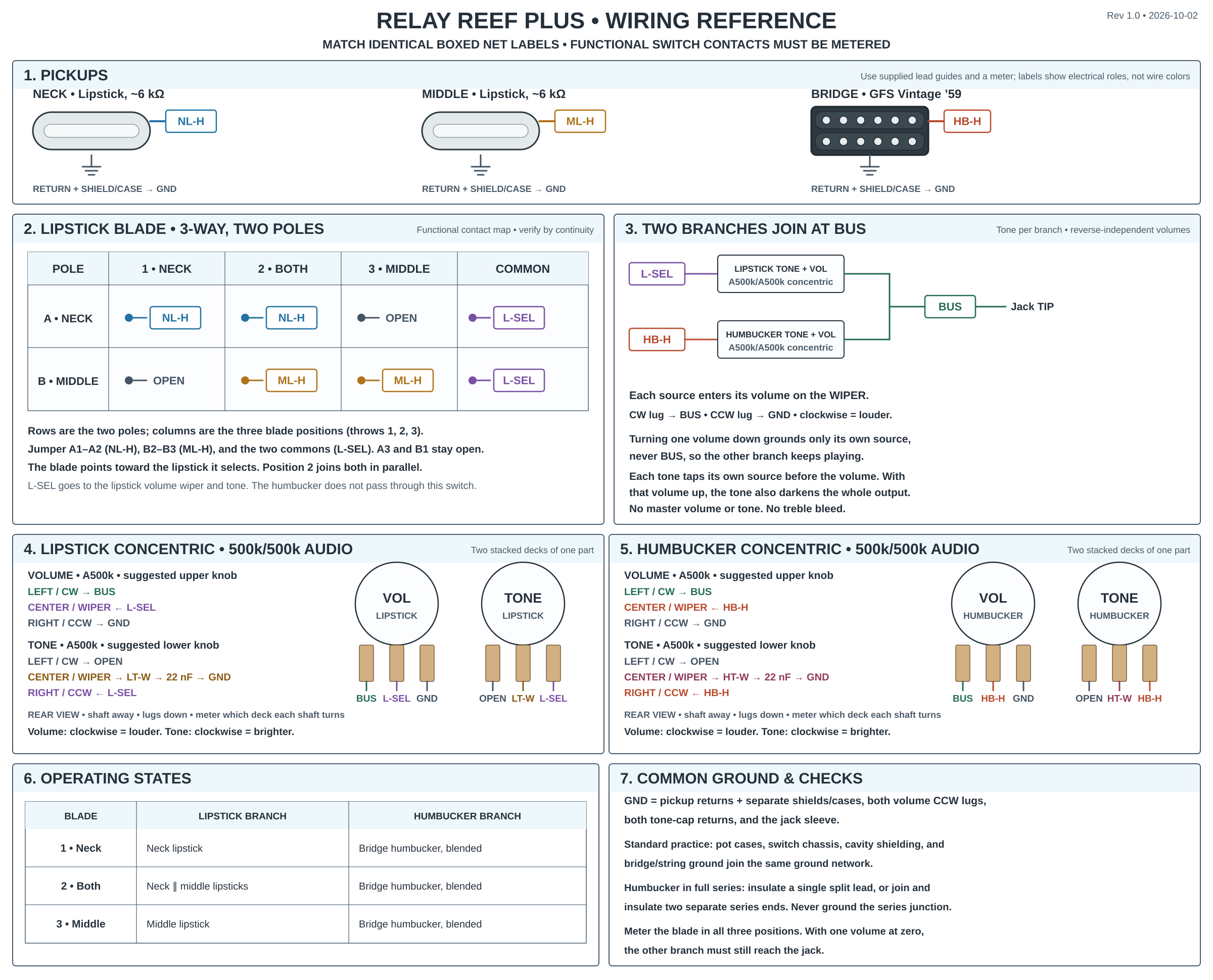
The 3-way blade is shown as a functional contact map, not the physical lug layout of a particular switch. Identify the contacts on the parts in hand with a continuity meter. The diagram's colored paths show circuit roles, not guaranteed GFS lead colors.
What each switch position does
| 3-way blade | Lipstick branch | Humbucker branch |
|---|---|---|
| 1 — Neck | Neck lipstick | Bridge humbucker, blended by its own volume |
| 2 — Both | Neck + middle lipsticks in parallel | Bridge humbucker, blended by its own volume |
| 3 — Middle | Middle lipstick | Bridge humbucker, blended by its own volume |
The blade points toward the lipstick it selects. The humbucker is available in every position; set its volume to zero to hear the lipsticks alone, or set the lipstick volume to zero to hear the humbucker alone. The tones interact: with a branch's volume full up, its pickups connect straight to the output, so its tone darkens the whole output, including the other side. As that volume comes down, its tone acts more and more on its own side only.
Parts and lead identification
- Bridge: GFS Vintage ’59 humbucker, wired full series.
- Middle and neck: GFS Pro Tube lipsticks, around 6 kΩ each, with hot, return, and shield or case ground as supplied.
- Controls: Two-pole 3-way blade (vintage Fender style, eight lugs), two 500k/500k audio-taper concentric pots (CTS stacked, Allparts EP-4586-000), two 22 nF (
0.022 µF,223) tone capacitors, and a mono output jack.
Use the supplied guide for each pickup's actual lead version and confirm with a meter; wire colors are not interchangeable across pickup models. On the humbucker, insulate an unused single split lead, or join and insulate the two separate series ends when the pickup supplies those instead. Never ground the series junction. Keep a separate case or shield lead grounded.
Use the same concentric part on both sides. We suggest the upper knob for volume and the lower knob for tone; the wiring works either way. Meter which deck each shaft turns before you wire it; the decks are not always in the same order. The concentric pots have not been test-fitted in a Relay body yet: check the control-hole size and cavity depth before ordering.
Reef Plus uses stock audio-taper pots, unlike the 1 MΩ linear volumes of Relay Reef. On the Coupeville prototype, audio-taper volumes in this circuit gave an uneven sweep with a sudden drop near the top. Check the sweep on the bench before you install the harness.
Blade contacts
Each pole connects its common to one throw per position: throw 1 in position 1, throw 2 in position 2, throw 3 in position 3. The two lipstick hots use separate poles, so they never share a contact.
| Pole | Common | Throw 1 | Throw 2 | Throw 3 |
|---|---|---|---|---|
| A — Neck | AC = L-SEL | A1 = NL-H | A2 = NL-H | A3 (unused) |
| B — Middle | BC = L-SEL | B1 (unused) | B2 = ML-H | B3 = ML-H |
Connection map
Match the boxed labels in the diagram. Every GND symbol belongs to one common ground network.
| Node | Connect these points |
|---|---|
NL-H | Neck lipstick hot to blade A1; jumper A1 to A2. |
ML-H | Middle lipstick hot to blade B2; jumper B2 to B3. |
L-SEL | Blade AC jumpered to BC, then to the lipstick volume wiper and the lipstick tone CCW lug. |
LT-W | Lipstick tone wiper through a 22 nF capacitor to GND. |
HB-H | Bridge humbucker hot to the humbucker volume wiper and the humbucker tone CCW lug. It does not go through the blade. |
HT-W | Humbucker tone wiper through a 22 nF capacitor to GND. |
BUS | Lipstick volume CW lug ↔ humbucker volume CW lug ↔ output-jack tip. |
| Unconnected | Leave blade A3 and B1 and both tone CW lugs open, connected to nothing. Insulate the humbucker series junction; never ground it. |
GND | Pickup returns and separate shields/cases, both volume CCW lugs, both tone-cap returns, pot cases, conductive blade chassis, cavity shield, bridge/string ground, and jack sleeve. |
Pot orientation: In the rear view with shafts pointing away and solder lugs down, the physical left/center/right terminals are CW/wiper/CCW. The lipstick volume's left/center/right lugs are BUS/L-SEL/GND; the lipstick tone's are unused/LT-W/L-SEL. The humbucker volume's are BUS/HB-H/GND; the humbucker tone's are unused/HT-W/HB-H. The volumes are not standard volumes: the source goes to the wiper and the output comes from the CW lug. Both volumes get louder and both tones get brighter when turned clockwise.
Build outline
- Shield the cavity first.
- Identify the pickup leads and the actual blade contacts by continuity in all three positions.
- Build the harness on the bench: lipsticks to the blade with the two jumpers, the joined commons to the lipstick volume wiper and tone, the humbucker hot to the humbucker volume wiper and tone, both tone wipers through their 22 nF capacitors to ground, and both volume CW lugs to
BUSand the jack tip. Insulate the humbucker series junction and leave the unused blade throws and tone CW lugs open. - Run one clean ground scheme: tie shielding, pickup returns and shields, pot cases, both volume CCW lugs, both capacitor returns, and the jack sleeve into one ground network.
- Install the harness only after it passes the meter check and tap test.
Bench checks
- Meter the blade:
L-SELmust reach onlyNL-Hin position 1, bothNL-HandML-Hin position 2, and onlyML-Hin position 3. In positions 1 and 3,NL-HandML-Hmust not connect; in position 2 they join only throughL-SEL. - With the lipstick volume full up and the humbucker volume at zero, measure between jack tip and sleeve. Expect roughly 6 kΩ in positions 1 and 3 and roughly 3 kΩ in position 2. Measure the isolated lipsticks rather than treating these readings as pass/fail limits.
- With the humbucker volume full up and the lipstick volume at zero, expect roughly the humbucker's own resistance.
- With both volumes at zero, the tip does not reach ground: expect roughly 250 kΩ, the two 500 kΩ volume tracks in parallel. A short to ground here means a source is on an outer lug instead of the wiper.
- The tone capacitors block DC, so the tone settings do not change these readings.
- Tap-test each pickup at low amplifier volume. Turn each volume from stop to stop with the other volume full up: when the first volume reaches zero, the other branch must keep playing. Note any sudden drop near the top of the sweep.
- With the humbucker volume at zero and the lipstick volume up, turn the lipstick tone down: the lipsticks must darken. Repeat for the humbucker side. With both volumes full up, either tone darkens the whole output; that is expected.