
Wiring
Pick the voicing you're building and you'll get its bench-side wiring reference: the selector map, connection points, and the published harness.
Relay Arc places a GFS Retrotron Liverpool at the bridge, a GFS Dream 180 in the middle, and a GFS Vintage ’59 at the neck. A four-pole five-way super switch selects the pickups. Pulling the A500k tone control engages Arc Mode: the Liverpool takes a 680 pF series path, while the selected Dream 180 or Vintage ’59 can receive a partial split. The A500k master volume has a parallel 1 nF / 150 kΩ treble bleed; the modern master tone uses a 22 nF capacitor.
Open full size
Download PNG
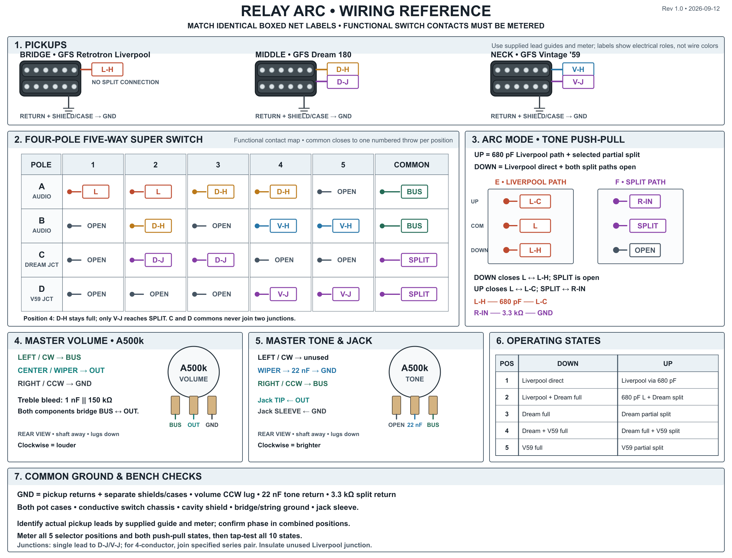
The super switch and tone push-pull show functional contact maps, not the physical solder-lug numbering of a particular switch. Identify the lugs on the parts in hand with a continuity meter. Colored paths identify circuit roles, not guaranteed GFS wire colors.
What each switch position does
| Five-way selector | Arc Mode down (tone pushed) | Arc Mode up (tone pulled) |
|---|---|---|
| 1 — Bridge | Liverpool full/direct | Liverpool full through 680 pF series capacitor |
| 2 — Bridge + middle | Liverpool direct + Dream full | Liverpool through 680 pF + Dream partially split |
| 3 — Middle | Dream full | Dream partially split |
| 4 — Middle + neck | Dream full + Vintage ’59 full | Dream full + Vintage ’59 partially split |
| 5 — Neck | Vintage ’59 full | Vintage ’59 partially split |
Selected pickups combine in parallel. Arc Mode never splits the Liverpool. In position 4, the Dream 180 remains a full humbucker; only the Vintage ’59 reaches the partial-split resistor. Arc Mode's 680 pF capacitor is in series with Liverpool hot, so it affects only positions 1–2. It is not the 22 nF tone capacitor or the 1 nF treble-bleed capacitor.
Parts and lead identification
- Bridge: GFS Retrotron Liverpool, hot (
L-H) and coil return, plus separate shield/case ground if supplied. Its series junction is not used. Insulate a supplied single split lead; with a four-conductor version, join and insulate the specified series pair. - Middle: GFS Dream 180, hot (
D-H), coil return, separate shield/case ground, and accessible series junction (D-J). - Neck: GFS Vintage ’59, hot (
V-H), coil return, separate shield/case ground, and accessible series junction (V-J). - Switching: Four-pole five-position super switch and an A500k push-pull master tone. The switch mechanism and physical lug order must be verified by continuity.
- Components: A500k master volume; 680 pF Liverpool series capacitor; 3.3 kΩ partial-split resistor; 1 nF capacitor and 150 kΩ resistor in parallel for the volume treble bleed; 22 nF (
0.022 µF,223) tone capacitor; mono output jack.
A GFS harness may present its series junction as one external lead. Use that single lead for D-J or V-J. A conventional four-conductor harness exposes two separate series ends; join the maker's specified pair to form the junction. Confirm hot, return, junction, and shield on the supplied pickup guides and with a meter before soldering. Keep a separate metal cover or shield lead grounded rather than using it as a switchable coil return.
Super-switch contact map
For each pole, its common contacts the numbered throw matching the five-way blade position. This table is functional; find the physical lugs on the actual super switch by continuity.
| Pole | Common | Position 1 | Position 2 | Position 3 | Position 4 | Position 5 |
|---|---|---|---|---|---|---|
| A — audio | BUS | L | L | D-H | D-H | open |
| B — audio | BUS | open | D-H | open | V-H | V-H |
| C — Dream junction | SPLIT | open | D-J | D-J | open | open |
| D — Vintage junction | SPLIT | open | open | open | V-J | V-J |
Join the two audio commons at BUS and the two junction commons at SPLIT. Use the two audio poles to form the combined-pickup positions; do not solder two pickup hots together at one throw. The junction poles never select D-J and V-J in the same position.
Arc Mode push-pull contacts
The tone push-pull has two independent poles. The labels E and F identify their roles; they are not manufacturer lug numbers.
| Pole | Common | Down throw | Up throw |
|---|---|---|---|
| E — Liverpool path | L | L-H direct | L-C, the far side of the 680 pF series capacitor |
| F — partial split | SPLIT | open | R-IN, one end of 3.3 kΩ; the other end goes to GND |
Connect the near side of the 680 pF capacitor to L-H. Down, L meets L-H directly and SPLIT floats. Pulled up, L meets L-C through the capacitor and SPLIT reaches ground through 3.3 kΩ. Verify the actual lug pairs in both mechanical states before wiring the pickups.
Connection map
Match identical labels in the diagram. Every GND symbol belongs to one common ground network.
| Net | Connect these points |
|---|---|
L-H | Liverpool hot ↔ push-pull E down throw ↔ one side of the 680 pF capacitor. |
L-C | Other side of the 680 pF capacitor ↔ push-pull E up throw. |
L | Push-pull E common ↔ super-switch A throws 1 and 2. |
D-H | Dream hot ↔ super-switch A throws 3 and 4 ↔ B throw 2. |
V-H | Vintage hot ↔ super-switch B throws 4 and 5. |
D-J | Dream series junction ↔ super-switch C throws 2 and 3. |
V-J | Vintage series junction ↔ super-switch D throws 4 and 5. |
SPLIT | Super-switch C and D commons ↔ push-pull F common. |
BUS | Super-switch A and B commons ↔ volume left/CW input lug ↔ tone right/CCW feed lug ↔ one end of both treble-bleed components. |
OUT | Volume center/wiper lug ↔ jack tip ↔ other end of both treble-bleed components. |
GND | Pickup coil returns and separate shields/cases; 3.3 kΩ return; volume right/CCW lug; 22 nF tone-cap return; pot cases; conductive switch chassis; cavity shield; bridge/string ground; jack sleeve. |
Pot orientation: Both pots are shown from the rear, shafts away and lugs down. Physical left/center/right correspond to CW/wiper/CCW. Volume lugs are BUS/OUT/GND. Tone lugs are unused/22 nF capacitor to ground/BUS. The tone feed is on the volume input side (BUS), which is modern wiring. Clockwise should increase volume and brighten tone.
Treble bleed: Join one end of the 1 nF capacitor and one end of the 150 kΩ resistor at BUS; join their other ends at OUT. They are parallel across the volume input and wiper, separate from the Liverpool series capacitor and the tone branch.
Build sequence
- Identify and meter all pickup leads and switch contacts. Label the super-switch poles and five throws from actual continuity in every blade position; label the push-pull's two commons and throws in both mechanical states. Keep separate pickup shields or metal cases grounded.
- Wire the selector audio poles A and B to produce the five full-pickup selections. Complete
BUS, the A500k volume, the modern A500k tone branch, the jack, and common ground. Verify selection before adding Arc Mode. - Wire Dream
D-Jto C throws 2–3 and VintageV-Jto D throws 4–5. Join C and D commons atSPLIT; connect this to push-pull F common. Wire F up through 3.3 kΩ to ground and leave F down open. - Wire Liverpool
L-Hto E down and one side of 680 pF; connect the capacitor's far side (L-C) to E up, and E common (L) to A throws 1–2. Add the parallel 1 nF / 150 kΩ treble bleed fromBUStoOUT. - Bench-check all ten operating states before mounting the harness in the guitar.
Bench checks
- Meter each selector pole and the push-pull separately before attaching pickup leads. In position 4,
D-Jmust be isolated fromSPLIT, whileV-Jconnects to it.D-JandV-Jmust never be joined by the switch. - With Arc Mode down, neither series junction may reach the 3.3 kΩ resistor. With Arc Mode up, only Dream in positions 2–3 or Vintage in positions 4–5 may reach it. The Liverpool hot takes the direct path down and the 680 pF series path up.
- Confirm every designated ground reaches jack sleeve and that jack tip does not have a near-zero-ohm short to sleeve with volume up. At volume zero, jack tip should reach ground through the volume wiper. Capacitors block steady DC after a meter settles; use measured parts rather than fixed pickup-resistance targets.
- Tap-test at low amplifier volume in all ten states. Position 4 should keep Dream full while Vintage changes to the partial split. Confirm the Liverpool still sounds in positions 1–2 with Arc Mode up, and check the combined positions for unexpected phase cancellation.
- Turn the knobs from stop to stop: clockwise should increase volume and brighten the tone. Audition the treble bleed as volume rolls down before final installation.