
STR26002 · Rev 1.1 · September 25, 2026
CuNiFe S-Type wiring reference
The five-way selector keeps the familiar S-type choices. The small switch adds the neck pickup in parallel, providing bridge-and-neck and all-three-pickup combinations.
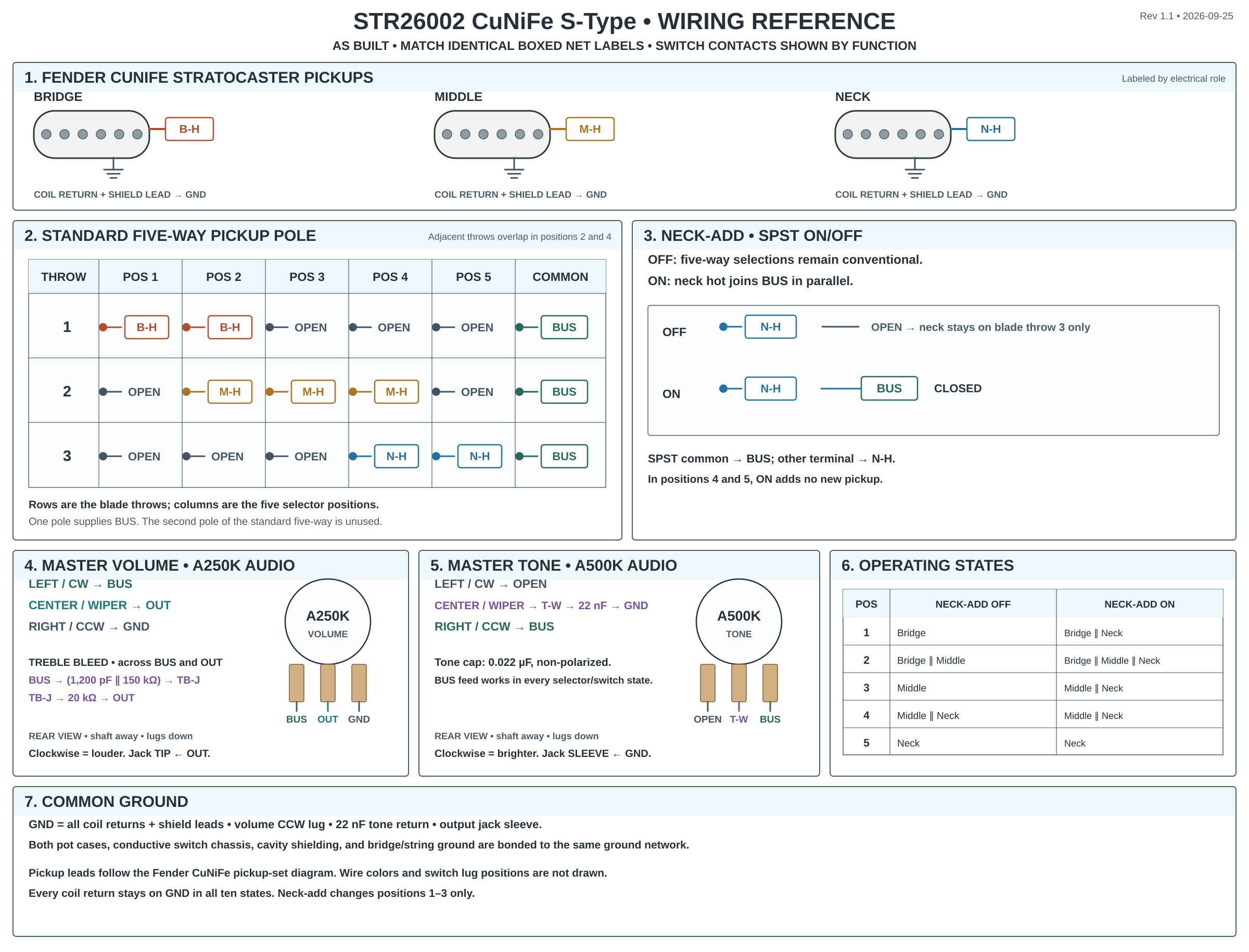
What each switch position does
| Five-way position | Neck-add off | Neck-add on |
|---|---|---|
| 1 | Bridge | Bridge and neck in parallel |
| 2 | Bridge and middle in parallel | Bridge, middle, and neck in parallel |
| 3 | Middle | Middle and neck in parallel |
| 4 | Middle and neck in parallel | Middle and neck in parallel |
| 5 | Neck | Neck |
Parts
Manufacturer pickup specifications: Fender CuNiFe pickup-set diagram.
- Fender CuNiFe Stratocaster bridge, middle, and neck pickups, each with an isolated shield lead.
- Standard five-way blade and latching SPST on-off micro switch.
- A250K audio-taper master volume, A500K audio-taper master tone, 22 nF (0.022 µF) non-polarized tone capacitor, and mono output jack.
- Treble bleed: a 1,200 pF capacitor in parallel with a 150 kΩ resistor, from the volume input, then a 20 kΩ resistor to the volume wiper.
Functional switch contacts
One pole of the standard five-way selects the pickups; the second pole is unused. Adjacent throws overlap in positions 2 and 4.
| Pole and common | 1 | 2 | 3 | 4 | 5 |
|---|---|---|---|---|---|
| Pickup pole / BUS | B-H | B-H + M-H | M-H | M-H + N-H | N-H |
The SPST connects neck hot N-H directly to BUS when on and leaves that path open when off. It adds no new pickup in positions 4 and 5 because the blade already selects the neck. All three coil returns stay grounded in every state.
Connection map
| Net | Connect these points |
|---|---|
| B-H | Bridge hot to the blade bridge throw. |
| M-H | Middle hot to the blade middle throw. |
| N-H | Neck hot to the blade neck throw and the SPST neck-add terminal. |
| BUS | Blade common, SPST common, volume input, master-tone feed, and treble-bleed input. |
| TB-J | The 1,200 pF capacitor and 150 kΩ resistor run in parallel from BUS to TB-J. The 20 kΩ resistor runs from TB-J to OUT. |
| T-W | The A500K tone wiper runs through the 22 nF capacitor to GND. The tone pot CCW lug takes BUS; its CW lug is unused. |
| OUT | Volume wiper, treble-bleed output, and output-jack tip. |
| GND | All three coil returns and shield leads; volume track ground; tone-cap return; pot and switch cases, cavity shield, bridge/string ground, and jack sleeve. |
In the diagram’s rear pot view, the shaft points away and the lugs point down. Left, center, and right are clockwise end, wiper, and counterclockwise end.